Product Introduction
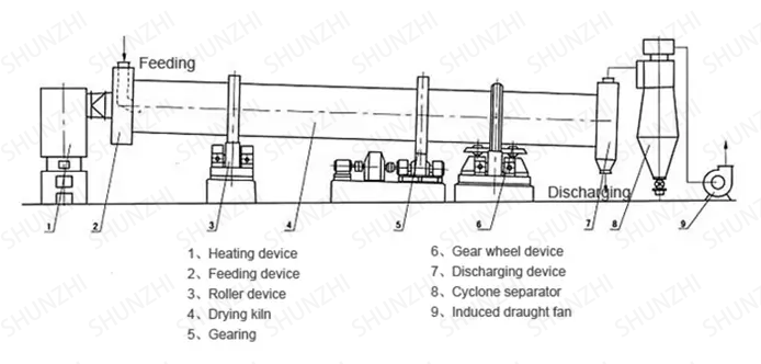
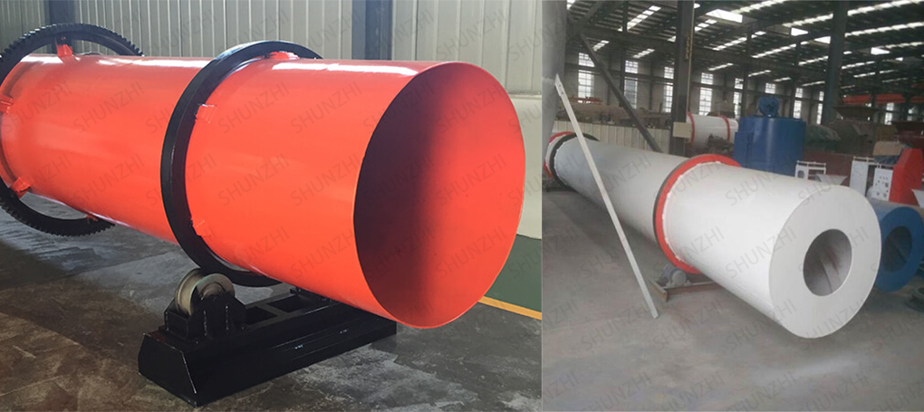
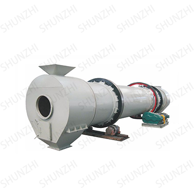
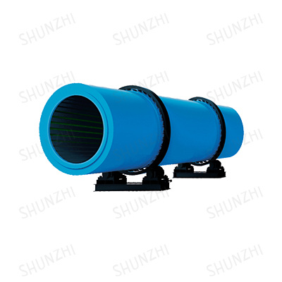
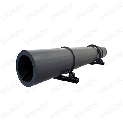
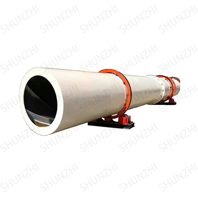
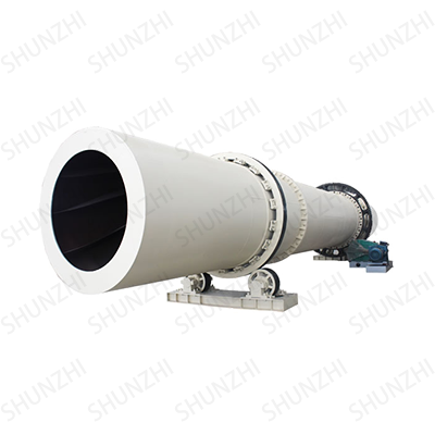
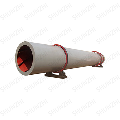
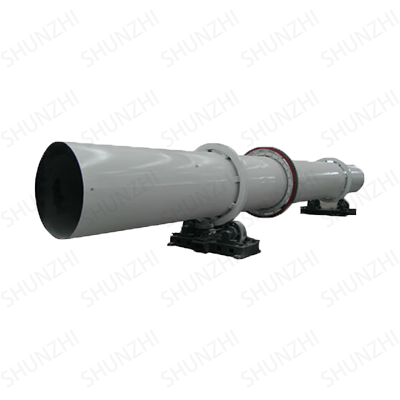
The fluorite powder dryer is mainly composed of rotating body, lifting plate, transmission device, supporting device and sealing ring.
The fluorite powder dryer is a cylinder slightly inclined to the horizontal direction. The material is added from the higher end, and the high-temperature hot flue gas flows into the cylinder concurrently with the material. As the cylinder rotates, the material runs to the lower end. The copy board on the inner wall of the cylinder picks up and sprinkles the material, which increases the contact surface between the material and the airflow, so as to increase the drying rate and promote the advancement of the material. The dried product is collected from the lower part of the bottom end.
Performance Advantage
1. The material of the cylinder is 16Mn, and the thickness is 20mm. When the production is abnormal or the instantaneous temperature is too high, the cylinder will not produce oxide scale, which can increase the life of the cylinder. It has good wear resistance, so under normal conditions, the cylinder will not be scrapped due to premature wear.
2. According to the characteristics of fluorite powder and the temperature of 800°, 600°, 400°, 200°, and 100° from the feeding end to the discharging end, the movable plate (anti-adhesion) and chain hammer are used to break the inside of the cylinder. Make the drying material as small particles or powder as possible at the outlet, which is convenient for entering the next process. The material of the lifting plate is 16Mn, and the thickness is 8mm.
3. Improve the lifting plate, structure and welding form to ensure that the lifting plate is prevented from breaking and falling off during the normal operation of the equipment.
4. The reducer adopts the national standard reducer produced in Zibo, which makes the accessories universal, and can be purchased anywhere, and a vibration motor is added to the feed trough.
5. The supporting roller is lubricated by grease filling. The transmission gear of the dryer is lubricated by a circulating lubrication device to ensure the lubrication effect.
6. A discharge cover is provided, and a device to prevent the lifting plate from falling off is installed in the cover to protect the normal operation of the belt conveyor.
7. Reasonable design of the feeding chute angle and large inclination guide plate and the use of inclined lifting plate to prevent the material from overflowing from the retaining ring.
8. The multiple flexible sealing structure between the inlet and outlet cover and the machine body is made of tin steel sheet, which can ensure that the dry gas cannot leak out under the condition of slight negative pressure.
9. A spring plate elastic connection method is adopted between the large gear ring and the drum to reduce the damage to the large and small gears caused by the impact load.
10. Rolling bearings are adopted for all the retaining wheels and supporting wheel devices, and all bearings are up to standard products.
Equipment Pictures
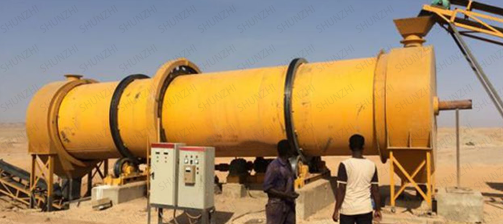
Customer Site
Technical Parameter
| Specification(m) | Cylinder volume | Capacity | Installation slope | Max intake air temperature | Main motor | Total weight |
| (Diameter x Length) | (m³) | (t/h) | (%) | (℃) | (kw) | (t) |
| Φ1.2×8.0 | 9 | 1.9-2.4 | 3-5 | 700-800 | 7.5 | 9 |
| Φ1.2×10 | 11.3 | 2.4-3.0 | 3-5 | 700-800 | 7.5 | 11 |
| Φ1.5×12 | 21.2 | 4.5-5.7 | 3-5 | 700-800 | 15 | 18.5 |
| Φ1.5×14 | 24.7 | 5.3-6.6 | 3-5 | 700-800 | 15 | 19.7 |
| Φ1.5×15 | 26.5 | 5.7-7.1 | 3-5 | 700-800 | 15 | 20.5 |
| Φ1.8×12 | 30.5 | 6.5-8.1 | 3-5 | 700-800 | 18.5 | 21.5 |
| Φ1.8×14 | 35.6 | 7.6-9.5 | 3-5 | 700-800 | 18.5 | 23 |
| Φ2.2×12 | 45.6 | 9.7-12.2 | 3-5 | 700-800 | 22 | 33.5 |
| Φ2.2×14 | 53.2 | 11.4-14.2 | 3-5 | 700-800 | 22 | 36 |
| Φ2.2×16 | 60.8 | 13.0-16.2 | 3-5 | 700-800 | 22 | 38 |
| Φ2.4×14 | 63.3 | 13.5-16.9 | 3-5 | 700-800 | 37 | 45 |
| Φ2.4×18 | 81.4 | 17.4-21.7 | 3-5 | 700-800 | 37 | 49 |
| Φ2.4×20 | 90.4 | 19.3-24.1 | 3-5 | 700-800 | 45 | 54 |
| Φ2.4×22 | 99.5 | 21.2-26.5 | 3-5 | 700-800 | 45 | 58 |
| Φ2.6×24 | 127.4 | 27.2-34.0 | 3-5 | 700-800 | 55 | 73 |
| Φ3.0×20 | 141.3 | 30.1-37.7 | 3-5 | 700-800 | 75 | 85 |
| Φ3.0×25 | 176.6 | 37.7-47.1 | 3-5 | 700-800 | 75 | 95 |
| Φ3.2×25 | 201 | 42.9-53.6 | 3-5 | 700-800 | 90 | 110 |
| Φ3.6×28 | 285 | 60.8-76.0 | 3-5 | 700-800 | 160 | 135 |
| Indirect heat transfer dryer | ||||||||
| Cylinder diameter × Cylinder length | Inner diameter of outer cylinder (mm) | Inner cylinder inner diameter (mm) | Cylinder length (m) | Cylinder volume (m³) | Cylinder slope | Lifting plate type | Maximum intake air temperature (℃) | Dimensions (m) |
| Φ1.5×15m | 1500 | 500 | 15 | 20.27 | 3-5% | lift type | 850 | 16.2×2.7×2.7 |
| Φ1.5×17m | 17 | 22.97 | 18.2×2.7×2.7 | |||||
| Φ1.5×19m | 19 | 25.68 | 20.0×2.9×2.9 | |||||
| Φ1.8×21m | 1800 | 650 | 21 | 35.91 | 3-5% | lift type | 850 | 22.5×2.7×2.7 |
| Φ1.8×23m | 23 | 39.33 | 24.5×2.9×2.9 | |||||
| Φ1.8×25m | 25 | 42.75 | 26.5×2.9×2.9 | |||||
| Φ2.2×21m | 2200 | 800 | 21 | 58.1 | 3-5% | lift type | 850 | ---- |
| Φ2.2×23m | 23 | 63.61 | ||||||
| Φ2.2×25m | 25 | 69.15 | ||||||

 TOP
TOP  Email
Email Phone
Phone Online