Product Introduction
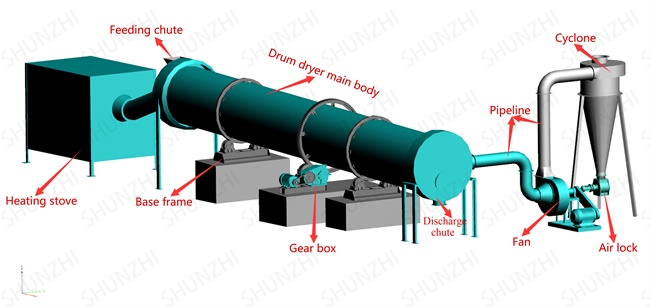
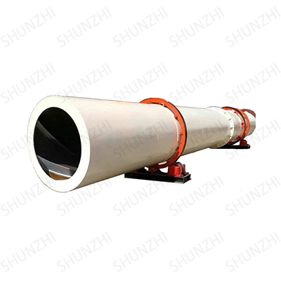
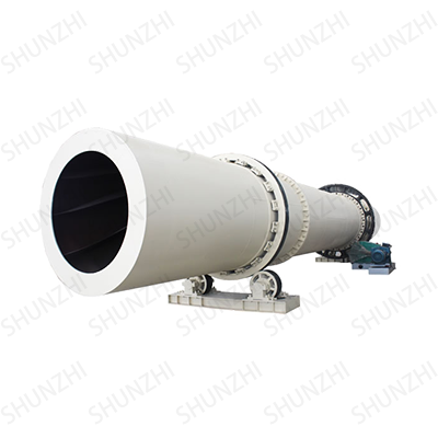
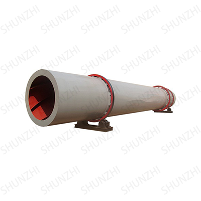
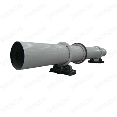
Organic fertilizer dryer is generally composed of cylinder, front roller ring, rear roller ring, gear, stop roller, drag roller, pinion, discharge part, lifting plate, reducer, motor, hot air duct, feeding chute, furnace body And other parts of the composition. The cylinder is driven by gears, and the speed is generally 2-6r/min, and the inclination of the cylinder is related to its length, usually between 1°-5°.
In the drying of organic fertilizers, rotary drum dryers are commonly used industrial drying equipment. The wet material enters the organic fertilizer dryer from the feed inlet and is heated by the hot air stove. The hot air generated is fully mixed with the organic fertilizer in the dryer for heat and mass exchange. The dried organic fertilizer is discharged from the outlet , The hot air with dust enters the cyclone dust collector and the bag filter for dust removal, and the purified air is discharged by the induced draft fan.
Performance Advantage
The internal structure design of the organic fertilizer dryer is reasonable, the contact area between the organic fertilizer particles and the hot air is large, and the organic fertilizer can fully exchange heat and dehydrate. The organic fertilizer can be fully mixed and agitated in the checkered plate, and the material falling time can be prolonged. Therefore, the contact time with the hot air is prolonged, which is beneficial to the residence time of the organic fertilizer in the drum and makes the organic fertilizer dehydration better.
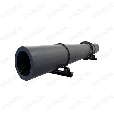
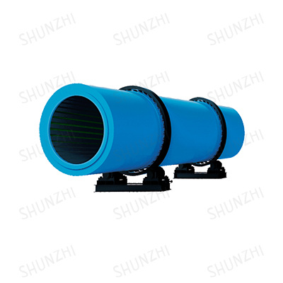
Equipment Pictures

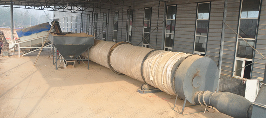
Customer Site
Technical Parameter
| Specification(m) | Cylinder volume | Capacity | Installation slope | Max intake air temperature | Main motor | Total weight |
| (Diameter x Length) | (m³) | (t/h) | (%) | (℃) | (kw) | (t) |
| Φ1.2×8.0 | 9 | 1.9-2.4 | 3-5 | 700-800 | 7.5 | 9 |
| Φ1.2×10 | 11.3 | 2.4-3.0 | 3-5 | 700-800 | 7.5 | 11 |
| Φ1.5×12 | 21.2 | 4.5-5.7 | 3-5 | 700-800 | 15 | 18.5 |
| Φ1.5×14 | 24.7 | 5.3-6.6 | 3-5 | 700-800 | 15 | 19.7 |
| Φ1.5×15 | 26.5 | 5.7-7.1 | 3-5 | 700-800 | 15 | 20.5 |
| Φ1.8×12 | 30.5 | 6.5-8.1 | 3-5 | 700-800 | 18.5 | 21.5 |
| Φ1.8×14 | 35.6 | 7.6-9.5 | 3-5 | 700-800 | 18.5 | 23 |
| Φ2.2×12 | 45.6 | 9.7-12.2 | 3-5 | 700-800 | 22 | 33.5 |
| Φ2.2×14 | 53.2 | 11.4-14.2 | 3-5 | 700-800 | 22 | 36 |
| Φ2.2×16 | 60.8 | 13.0-16.2 | 3-5 | 700-800 | 22 | 38 |
| Φ2.4×14 | 63.3 | 13.5-16.9 | 3-5 | 700-800 | 37 | 45 |
| Φ2.4×18 | 81.4 | 17.4-21.7 | 3-5 | 700-800 | 37 | 49 |
| Φ2.4×20 | 90.4 | 19.3-24.1 | 3-5 | 700-800 | 45 | 54 |
| Φ2.4×22 | 99.5 | 21.2-26.5 | 3-5 | 700-800 | 45 | 58 |
| Φ2.6×24 | 127.4 | 27.2-34.0 | 3-5 | 700-800 | 55 | 73 |
| Φ3.0×20 | 141.3 | 30.1-37.7 | 3-5 | 700-800 | 75 | 85 |
| Φ3.0×25 | 176.6 | 37.7-47.1 | 3-5 | 700-800 | 75 | 95 |
| Φ3.2×25 | 201 | 42.9-53.6 | 3-5 | 700-800 | 90 | 110 |
| Φ3.6×28 | 285 | 60.8-76.0 | 3-5 | 700-800 | 160 | 135 |
| Indirect heat transfer dryer | ||||||||
| Cylinder diameter × Cylinder length | Inner diameter of outer cylinder (mm) | Inner cylinder inner diameter (mm) | Cylinder length (m) | Cylinder volume (m³) | Cylinder slope | Lifting plate type | Maximum intake air temperature (℃) | Dimensions (m) |
| Φ1.5×15m | 1500 | 500 | 15 | 20.27 | 3-5% | lift type | 850 | 16.2×2.7×2.7 |
| Φ1.5×17m | 17 | 22.97 | 18.2×2.7×2.7 | |||||
| Φ1.5×19m | 19 | 25.68 | 20.0×2.9×2.9 | |||||
| Φ1.8×21m | 1800 | 650 | 21 | 35.91 | 3-5% | lift type | 850 | 22.5×2.7×2.7 |
| Φ1.8×23m | 23 | 39.33 | 24.5×2.9×2.9 | |||||
| Φ1.8×25m | 25 | 42.75 | 26.5×2.9×2.9 | |||||
| Φ2.2×21m | 2200 | 800 | 21 | 58.1 | 3-5% | lift type | 850 | ---- |
| Φ2.2×23m | 23 | 63.61 | ||||||
| Φ2.2×25m | 25 | 69.15 | ||||||

 TOP
TOP  Email
Email Phone
Phone Online